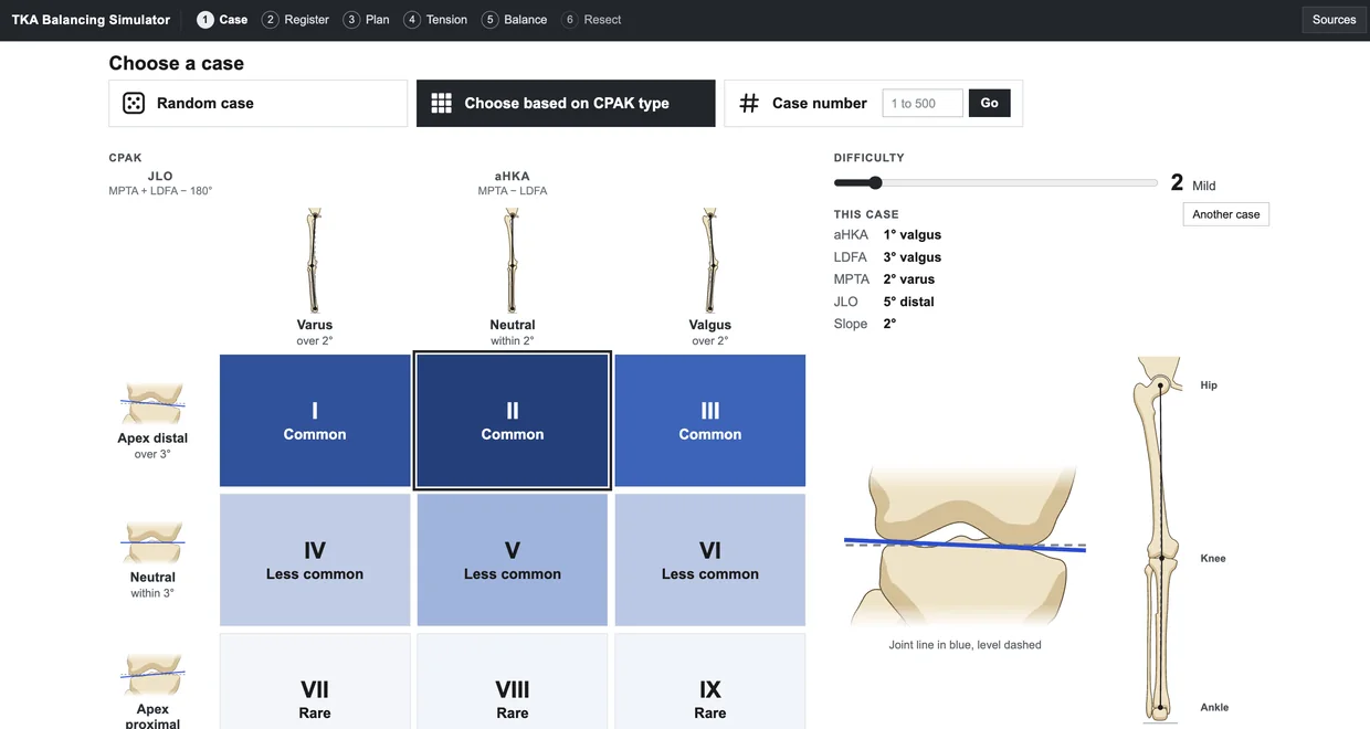
The case selection screen, with a three by three CPAK grid, a difficulty slider and the alignment of the selected case

Case library

The library contains 500 simulated arthritic knees distributed across all nine phenotypes of the Coronal Plane Alignment of the Knee (CPAK) classification described by MacDessi et al. (2021), in proportions similar to those reported in patients with knee arthritis. Each case has its own alignment, joint line obliquity and tibial slope, and cases can be selected at random, by CPAK type or by case number.

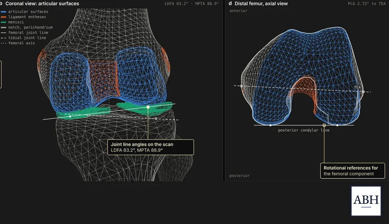
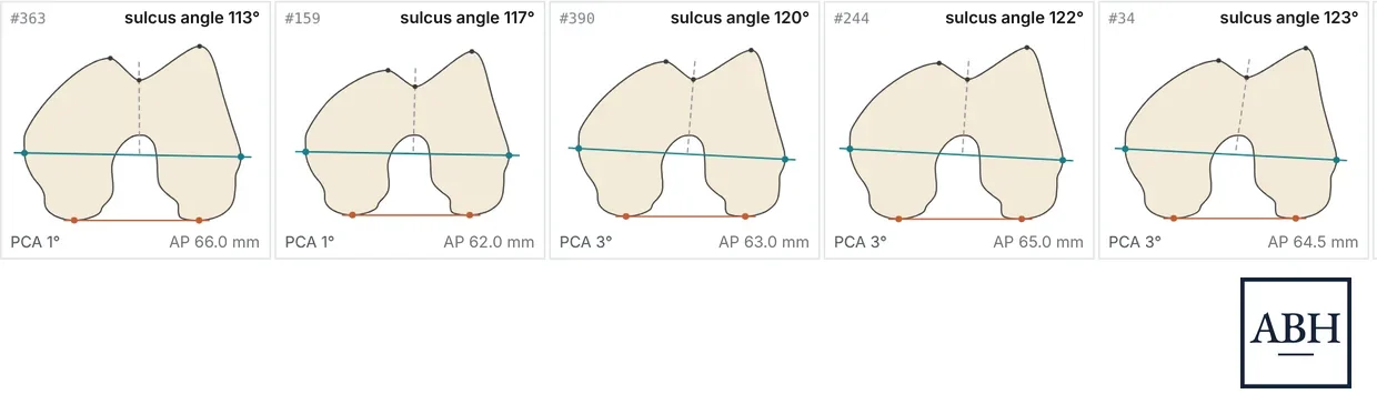
The scanned knee as a 3D mesh, from the front with its joint surfaces and ligament attachments, and the end of the femur with its rotational reference linesFive distal femurs viewed end on, each with a different trochlear groove angle, posterior condylar angle and size

Anatomy

Bone geometry was derived from a CT scan of an adult knee, and each outline was traced to within 0.1 mm of the scanned surface. This anatomy is adjusted to the alignment, size and tibial slope of each case. As a result, every knee has its own femoral rotation, trochlear groove morphology and anteroposterior dimensions.

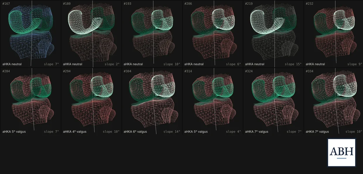
Twelve simulated knees shown as 3D meshes, with cartilage shaded from intact to worn away and bone tinted by alignment

Cartilage and arthritic change

Cartilage thickness varies by site, and wear follows the deformity, ranging from partial thinning to exposed bone. Higher levels of difficulty introduce flexion contracture, ligament contracture or stretch, and posterior osteophytes that differ in size between the medial and lateral compartments. During registration, the probe contacts whatever surface remains, which may be cartilage or bone.

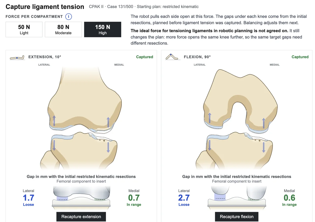
The ligament tension screen, with a choice of distraction force and the medial and lateral gaps captured in extension and in flexion

Ligament tension

Each compartment is distracted in extension and at 90° of flexion using a selected force, and the resulting opening reflects the laxity of that compartment. The gaps are then displayed for the planned components before any adjustments are made.

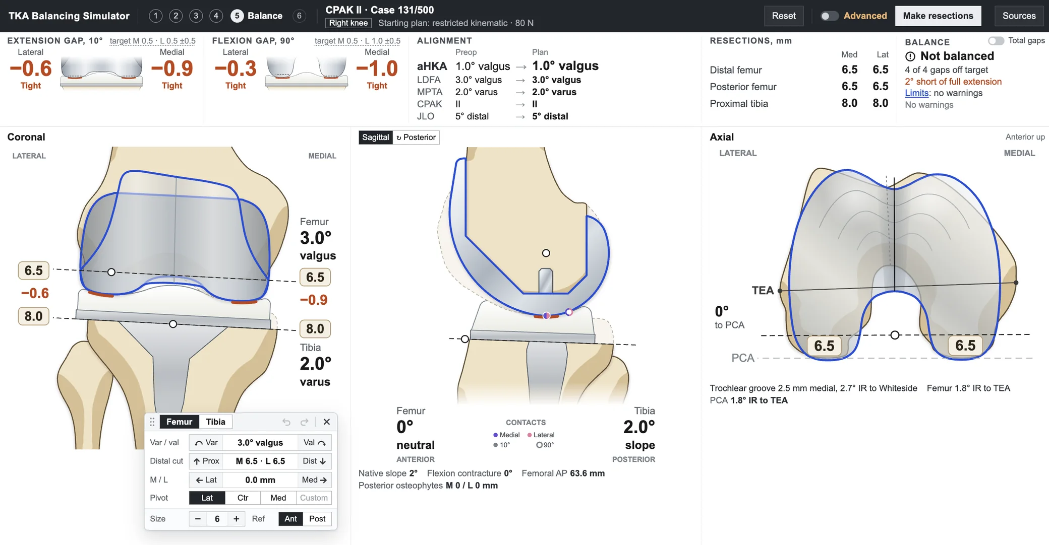
The balancing screen, with extension and flexion gaps, alignment and resections across the top and the knee in coronal, sagittal and axial views

Balancing

The femoral and tibial components can be adjusted in the coronal, sagittal and axial planes about a selected pivot point, and all four gaps, the resulting alignment, the resection depths and the alignment limits are updated with each change. Femoral rotation is displayed relative to the transepicondylar axis, the posterior condylar axis and Whiteside’s line. Soft tissue releases, removal of posterior osteophytes and posterior capsular release each alter the gaps, and the final report compares the result with the native knee at each site.

The model is based on published anatomical and biomechanical studies and is independent of any manufacturer’s system. Bone shapes were adapted from the Human Reference Atlas 3D library (HuBMAP) under a CC BY 4.0 license.

Open the simulator →

Educational simulation with a simplified model and a generic implant. Not for surgical planning. Not a medical device. All cases are fictional.